Job
Job Scheduling
A batch of pods that must be scheduled together is called a Job.
PodGroup
Sometimes, the batch of pods is completely homogeneous and only needs to accumulate to a specified minimum number before scheduling is successful. In this case, we can describe the minMember through a separate PodGroup, and then associate its member pods through pod Labels. Here is a PodGroup with a minimum cumulative number of 2 and its member pods.
apiVersion: scheduling.sigs.k8s.io/v1alpha1
kind: PodGroup
metadata:
  name: gang-example
  namespace: default
spec:
  minMember: 2
apiVersion: v1
kind: pod
metadata:
  name: pod-example1
  namespace: default
  labels:
    pod-group.scheduling.sigs.k8s.io: gang-example
spec:
  schedulerName: koord-scheduler
  ...
---
apiVersion: v1
kind: pod
metadata:
  name: pod-example2
  namespace: default
  labels:
    pod-group.scheduling.sigs.k8s.io: gang-example
spec:
  schedulerName: koord-scheduler
  ...
GangGroup
In other cases, the pods that must be scheduled together may not be homogeneous and must complete the minimum number of accumulations separately. In this case, Koordinator supports associating different PodGroups to form a GangGroup through PodGroup Label. Here is a GangGroup with two PodGroups:
apiVersion: scheduling.sigs.k8s.io/v1alpha1
kind: PodGroup
metadata:
  name: gang-example1
  namespace: default
  annotations:
    gang.scheduling.koordinator.sh/groups: "[\"default/gang-example1\", \"default/gang-example2\"]"
spec:
  minMember: 1
---
apiVersion: scheduling.sigs.k8s.io/v1alpha1
kind: PodGroup
metadata:
  name: gang-example2
  namespace: default
  annotations:
    gang.scheduling.koordinator.sh/groups: "[\"default/gang-example1\", \"default/gang-example2\"]"
spec:
  minMember: 2
Job-Level Preemption
When a pod cannot be scheduled due to insufficient resources, Kube-Scheduler attempts to evict lower-priority pods to make room for it. This is traditional pod-level reemption. However, when a Job cannot be scheduled due to insufficient resources, the scheduler must make enough space for the entire Job to be scheduled. This type of preemption is called Job-level preemption.
Preemption Algorithm
The job that initiates preemption is called the preemptor, and the preempted pod is called the victim. The overall workflow of job-level preemption is as follows:
- Unschedulable pod → Enters PostFilter phase
- Is it a Job? → Yes → Fetch all member pods
- Check Job Preemption Eligibility:
pods.spec.preemptionPolicy≠ Never- No terminating victims on the currently nominated nodes of all member pods (prevent redundant preemption)
- Find candidate nodes where preemption may help
- Perform dry-run to simulate removal of potential victims (low priority pods)
- Select optimal node + minimal-cost victim set (job-aware cost model)
- Execute preemption:
- Delete victims (by setting DisruptionTarget condition and invoking the deletion API)
- Clear
status.nominatedNodeof other lower-priority nominated pods on the target nodes. - Set
status.nominatedNodefor all member pods.
- Preemption successful → The pod enters the scheduling queue, waiting for victims to terminate.
Preemption Reason for Victim
When a victim is preempted, Koord-Scheduler adds an entry to victim.status.conditions to indicate which job preempted it and triggers graceful termination.
apiVersion: v1
kind: pod
metadata:
  name: victim-1
  namespace: default
status:
  conditions:
  - lastProbeTime: null
    lastTransitionTime: "2025-09-17T08:41:35Z"
    message: 'koord-scheduler: preempting to accommodate higher priority pods, preemptor:
      default/hello-job, triggerpod: default/preemptor-pod-2'
    reason: PreemptionByScheduler
    status: "True"
    type: DisruptionTarget
The above shows that default/victim-1 was preempted by the high-priority job hello-job. Member Pods of hello-job can be retrieved via the following command:
$ kubectl get po -n default -l pod-group.scheduling.sigs.k8s.io=hello-job
hello-job-pod-1   0/1     Pending             0                5m
hello-job-pod-2   0/1     Pending             0                5m
Nominated Node for Preemptor
After a Job preemption succeeds, in addition to evicting the victim pods, the scheduler must also reserve the reclaimed resources in its internal cache. In Kubernetes, this is achieved using pod.status.nominatedNode. In Koordinator, koord-scheduler sets the .status.nominatedNode field for all member pods of the preempting job to reflect this resource reservation.
apiVersion: v1
kind: pod
metadata:
name: preemptor-pod-1
namespace: default
labels:
  pod-group.scheduling.sigs.k8s.io: hello-job
status:
  nominatednodeName: example-node
  phase: Pending
---
apiVersion: v1
kind: pod
metadata:
  name: preemptor-pod-2
  namespace: default
  labels:
    pod-group.scheduling.sigs.k8s.io: hello-job
status:
  nominatednodeName: example-node
  phase: Pending
The above shows that the two pods of hello-job have successfully completed preemption and are nominated for scheduling to example-node.
Network-Topology Aware
In large-scale AI training scenarios, especially for large language models (LLMs), efficient inter-pod communication is critical to training performance. Model parallelism techniques such as Tensor Parallelism (TP), Pipeline Parallelism (PP), and Data Parallelism (DP) require frequent and high-bandwidth data exchange across GPUs—often spanning multiple nodes. Under such workloads, network topology becomes a key performance bottleneck, where communication latency and bandwidth are heavily influenced by the physical network hierarchy (e.g., NVLink, block, spine).
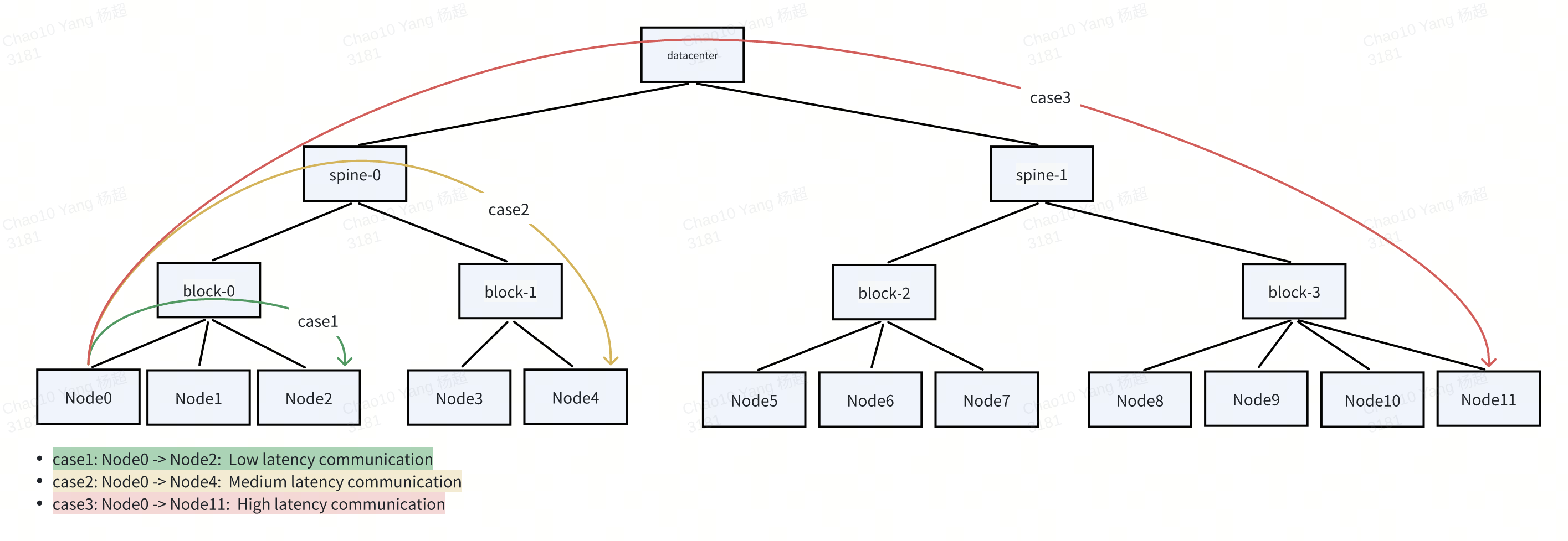
To optimize training efficiency, pods within a GangGroup is required or preferred to be scheduled to nodes that reside in the same or nearby high-performance network domains, minimizing inter-node hops and maximizing throughput. For example, in a spine-block architecture, scheduling all member pods under the same block or spine switch significantly reduces communication latency compared to distributing them across different spines.
Topology-Aware Scheduling Requirements
While Kubernetes’ native scheduler supports basic topology constraints via PodAffinity, it operates on a per-Pod basis and lacks gang scheduling semantics, making it ineffective for coordinated placement of tightly coupled workloads. Koord-Scheduler abstracts PodGroup and GangGroup concept to providing all-or-nothing semantics, enabling collective scheduling of interdependent pods. Moreover, to meet the demands of modern AI training, we extend it with Network-Topology Aware Scheduling—a capability that intelligently selects optimal nodes based on network hierarchy.
This feature ensures:
- When cluster resources are sufficient, pods with network topology scheduling requirements will be scheduled to a topology domain with better performance (e.g., lower latency, higher bandwidth) according to user-specified strategies.
- When cluster resources are insufficient, the scheduler will seize resources for the GangGroup based on network topology constraints through job-level preemption, and record the resource nominations in the
.status.nominatedNodefield to ensure consistent placement.
Cluster Network Topology
Nodes are labeled with their network topology positions using tools like NVIDIA’s topograph:
apiVersion: v1
kind: Node
metadata:
  name: node-0
  labels:
    network.topology.nvidia.com/accelerator: nvl1
    network.topology.nvidia.com/block: s1
    network.topology.nvidia.com/spine: s2
    network.topology.nvidia.com/datacenter: s3
Administrators define the topology hierarchy via a ClusterNetworkTopology CR named default:
apiVersion: scheduling.koordinator.sh/v1alpha1
kind: ClusterNetworkTopology
metadata:
  name: default
spec:
  networkTopologySpec:
    - labelKey:
      - network.topology.nvidia.com/spine
      topologyLayer: SpineLayer
    - labelKey:
      - network.topology.nvidia.com/block
      parentTopologyLayer: SpineLayer
      topologyLayer: BlockLayer
    - parentTopologyLayer: BlockLayer
      topologyLayer: NodeTopologyLayer
The topology forms a tree structure, where each layer represents a level of aggregation in the network (e.g., Node → block → spine).
The status.detailStatus field of ClusterNetworkTopology is automatically maintained by Koordinator, reflecting the actual network topology structure and node distribution in the cluster. It presents a hierarchical view from the top-level (cluster) down to individual nodes. Each entry in detailStatus represents an instance of a specific topology layer, with key fields:
topologyInfo: The current layer's type and name (e.g.,SpineLayer,s1).parentTopologyInfo: The parent layer’s information.childTopologyNames: List of child domains in the next lower layer.nodeNum: Number of nodes within this topology domain.
The follwing is an example of clusterNetworkTopology.status.detailStatus:
apiVersion: scheduling.koordinator.sh/v1alpha1
kind: ClusterNetworkTopology
metadata:
  name: default
spec:
  networkTopologySpec:
  - labelKey:
    - network.topology.nvidia.com/spine
    topologyLayer: SpineLayer
  - labelKey:
    - network.topology.nvidia.com/block
    parentTopologyLayer: SpineLayer
    topologyLayer: BlockLayer
  - parentTopologyLayer: BlockLayer
    topologyLayer: NodeTopologyLayer
status:
  detailStatus:
  - childTopologyLayer: SpineLayer
    childTopologyNames:
    - s1
    - s2
    nodeNum: 8
    topologyInfo:
      topologyLayer: ClusterTopologyLayer
      topologyName: ""
  - childTopologyLayer: BlockLayer
    childTopologyNames:
    - b2
    - b1
    nodeNum: 4
    parentTopologyInfo:
      topologyLayer: ClusterTopologyLayer
      topologyName: ""
    topologyInfo:
      topologyLayer: SpineLayer
      topologyName: s1
  - childTopologyLayer: NodeTopologyLayer
    nodeNum: 2
    parentTopologyInfo:
      topologyLayer: SpineLayer
      topologyName: s1
    topologyInfo:
      topologyLayer: BlockLayer
      topologyName: b2
  - childTopologyLayer: NodeTopologyLayer
    nodeNum: 2
    parentTopologyInfo:
      topologyLayer: SpineLayer
      topologyName: s1
    topologyInfo:
      topologyLayer: BlockLayer
      topologyName: b1
  - childTopologyLayer: BlockLayer
    childTopologyNames:
    - b3
    - b4
    nodeNum: 4
    parentTopologyInfo:
      topologyLayer: ClusterTopologyLayer
      topologyName: ""
    topologyInfo:
      topologyLayer: SpineLayer
      topologyName: s2
  - childTopologyLayer: NodeTopologyLayer
    nodeNum: 2
    parentTopologyInfo:
      topologyLayer: SpineLayer
      topologyName: s2
    topologyInfo:
      topologyLayer: BlockLayer
      topologyName: b3
  - childTopologyLayer: NodeTopologyLayer
    nodeNum: 2
    parentTopologyInfo:
      topologyLayer: SpineLayer
      topologyName: s2
    topologyInfo:
      topologyLayer: BlockLayer
      topologyName: b4
Based on the above status, the cluster has a two-tier spine-block architecture:
ClusterTopologyLayer
├── SpineLayer: s1
│   ├── BlockLayer: b1
│   │   └── NodeTopologyLayer: 2 nodes
│   └── BlockLayer: b2
│       └── NodeTopologyLayer: 2 nodes
└── SpineLayer: s2
    ├── BlockLayer: b3
    │   └── NodeTopologyLayer: 2 nodes
    └── BlockLayer: b4
        └── NodeTopologyLayer: 2 nodes
Network Topology Spec
When users want to configure the network topology gather strategy for GangGroup, its PodGroup can be annotated as follows:
apiVersion: scheduling.sigs.k8s.io/v1alpha1
kind: PodGroup
metadata:
  name: gang-master
  namespace: default
  annotations:
    gang.scheduling.koordinator.sh/groups: ["default/gang-master", "default/gang-worker"]
    gang.scheduling.koordinator.sh/network-topology-spec: |
      {
        "gatherStrategy": [
          {
            "layer": "SpineLayer",
            "strategy": "PreferGather"
          },
          {
            "layer": "BlockLayer",
            "strategy": "PreferGather"
          },
          {
            "layer": "AcceleratorLayer",
            "strategy": "PreferGather"
          }
        ]
      }
spec:
  minMember: 1
---
apiVersion: scheduling.sigs.k8s.io/v1alpha1
kind: PodGroup
metadata:
  name: gang-worker
  namespace: default
  annotations:
    gang.scheduling.koordinator.sh/groups: ["default/gang-master", "default/gang-worker"]
    gang.scheduling.koordinator.sh/network-topology-spec: |
      {
        "gatherStrategy": [
          {
            "layer": "SpineLayer",
            "strategy": "PreferGather"
          },
          {
            "layer": "BlockLayer",
            "strategy": "PreferGather"
          },
          {
            "layer": "AcceleratorLayer",
            "strategy": "PreferGather"
          }
        ]
      }
spec:
  minMember: 2
The above PodGroup indicates that the Pods belonging to it firstly try to be in an accelerator interconnection domain, and then try to be in a Block, and then try to be in a Spine network.
PodCountMultiple
In some distributed training scenarios, the number of Pods placed within each topology domain must be a multiple of a specific value X, where X is related to communication parameters (e.g., Tensor Parallelism degree) within the domain. For example, if TP=8, then each Block should contain exactly 0 or 8 Pods—never a partial group. This can be configured via the podCountMultiple field in the gather strategy:
apiVersion: scheduling.sigs.k8s.io/v1alpha1
kind: PodGroup
metadata:
  name: gang-example
  namespace: default
  annotations:
    gang.scheduling.koordinator.sh/network-topology-spec: |
      {
        "gatherStrategy": [
          {
            "layer": "SpineLayer",
            "strategy": "PreferGather"
          },
          {
            "layer": "BlockLayer",
            "strategy": "PreferGather",
            "podCountMultiple": 8
          }
        ]
      }
spec:
  minMember: 16
In the above example, podCountMultiple: 8 at the BlockLayer means that the number of Pods assigned to each Block must be a multiple of 8. When calculating offerslots, the algorithm constrains each topology node's offerslots to be rounded down to the nearest multiple of the specified podCountMultiple value for that layer.
Sometimes, due to the strict demand for communication bandwidth, users may want to place all member Pods of a GangGroup under the same Spine. In this case, you can modify the PodGroup as follows:
apiVersion: scheduling.sigs.k8s.io/v1alpha1
kind: PodGroup
metadata:
  name: gang-master
  namespace: default
  annotations:
    gang.scheduling.koordinator.sh/groups: ["default/gang-master", "default/gang-worker"]
    gang.scheduling.koordinator.sh/network-topology-spec: |
      {
        "gatherStrategy": [
          {
            "layer": "spineLayer",
            "strategy": "MustGather"
          }
        ]
      }
spec:
  minMember: 1
---
apiVersion: scheduling.sigs.k8s.io/v1alpha1
kind: PodGroup
metadata:
  name: gang-worker
  namespace: default
  annotations:
    gang.scheduling.koordinator.sh/groups: ["default/gang-master", "default/gang-worker"]
    gang.scheduling.koordinator.sh/network-topology-spec: |
      {
        "gatherStrategy": [
          {
            "layer": "spineLayer",
            "strategy": "MustGather"
          }
        ]
      }
spec:
  minMember: 2
Network Topology Pod Index
In distributed training, assigning an index to each Pod is essential for establishing communication patterns in data-parallel (DP) job. The index determines the logical order of Pods in collective operations. For example, for a GangGroup with DP=2, the member pods can be annotated as:
apiVersion: v1
kind: Pod
metadata:
  name: pod-example1
  namespace: default
  labels:
    pod-group.scheduling.sigs.k8s.io: gang-example
  annotations:
    gang.scheduling.koordinator.sh/network-topology-index: "1"
spec:
  schedulerName: koord-scheduler
...
---
apiVersion: v1
kind: Pod
metadata:
  name: pod-example2
  namespace: default
  labels:
    pod-group.scheduling.sigs.k8s.io: gang-example
  annotations:
    gang.scheduling.koordinator.sh/network-topology-index: "2"
spec:
  schedulerName: koord-scheduler
...
Topology Gather Algorithm
The network topology gather algorithm is to find the best nodes for the M Pods, given the M member Pods belonging to a parallel-aware GangGroup, all the Nodes that can place the Pods, the network topology location of each node. The overall computation process can be described step by step as follows:
The member Pods of the
GangGroupof the training task are generally homogeneous. We randomly select one from the member Pods as the representative Pod.From the bottom to the top of the network topology hierarchy, recursively calculate the number of member Pods that each topology node can provide as
offerslots. Theofferslotsthat a Node can accommodate can be achieved by iteratively callingNodeInfo.AddPod,fwk.RunPreFilterExtensionsAddPod, andfwk.RunFilterWithNominatedNode.Among all the topological nodes that can accommodate all the member Pods of the
GangGroup, select those with the lowest level as ourcandidate topological nodes.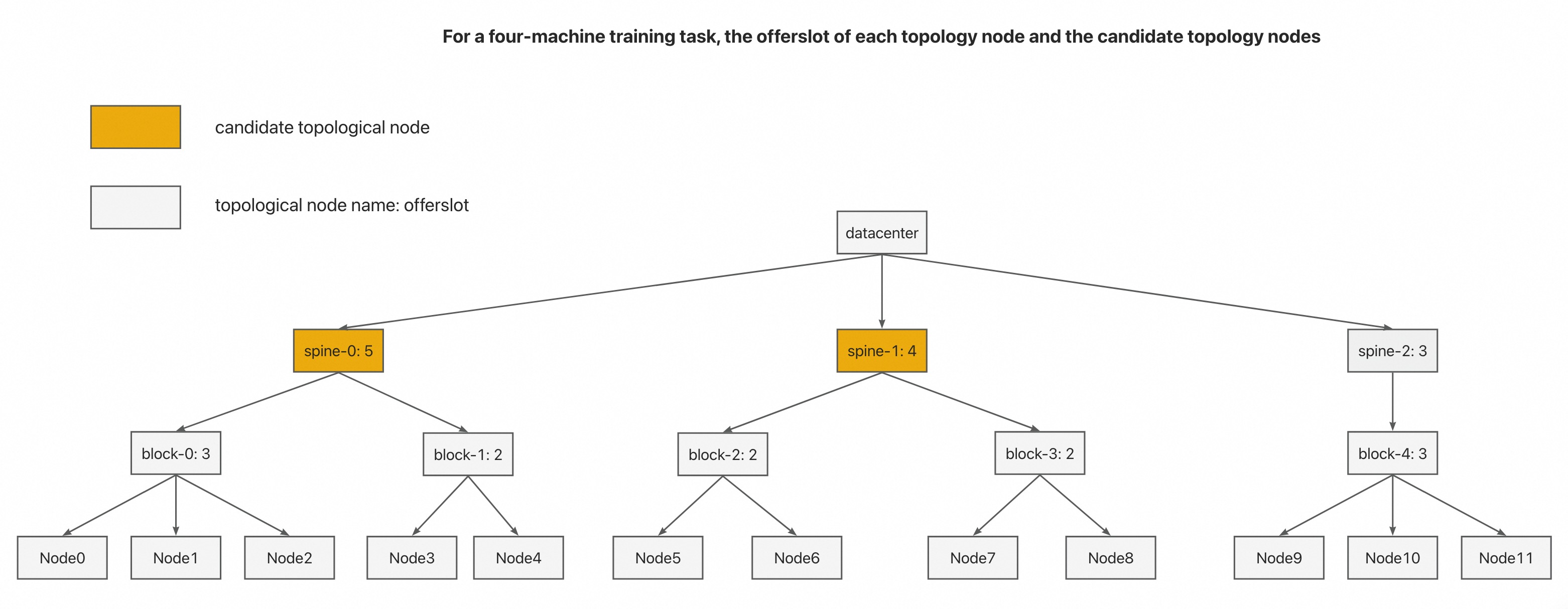
Among the candidate topological nodes selected in 3, according to the
binpackprinciple, the candidate topological nodes whose offerslot is closest to the offerslot required by the job are selected as our final topological node solution. As shown in the figure below, we select Node5-Node8 as the final scheduling result of the job.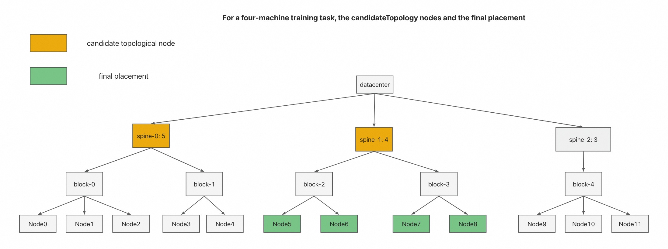
What's Next
- Gang Scheduling: Learn how to enable gang scheduling for your application.
- Network Topology Aware Scheduling: Learn how to enable network topology aware scheduling for gang.
- Job Level Preemption: Learn how to use Job Level Preemption